ColdFlow covers everything up to hot fire: sizing, regenerative cooling, injector design, geometry, laser powder-bed fusion print rules, cold-flow CFD and mesh verification. Engines are registered as design variants, so the same physics and geometry code serves every engine.
There are two so far. The 50 N runs nitrous oxide and LPG at 11 bar and has passed its verification gate. The 5 kN runs nitrous oxide and ethanol at 15 bar, in CuCrZr, at a hundred times the thrust: a sized concept with a thermal march, print audit and cold-flow CFD. Neither has been hot-fired.
- Propellant
- Nitrous oxide with LPG or ethanol
- Cooling
- Regenerative, Bartz gas-side heat flux
- Material
- AlSi10Mg and CuCrZr, laser powder-bed fusion
A 50 N head solved, printed to rule and verified end to end
The smallest engine is the most complete. Its propellant passages, regenerative cooling, injector, torch igniter and print rules all come from one solved design: the head layout is placed by a certified solver against a set of contracts, not drawn by hand. Passages are self-supporting teardrops, threads are tapped after printing, and a verification gate checks wall thickness and every contract on the finished fields before anything is called a result.
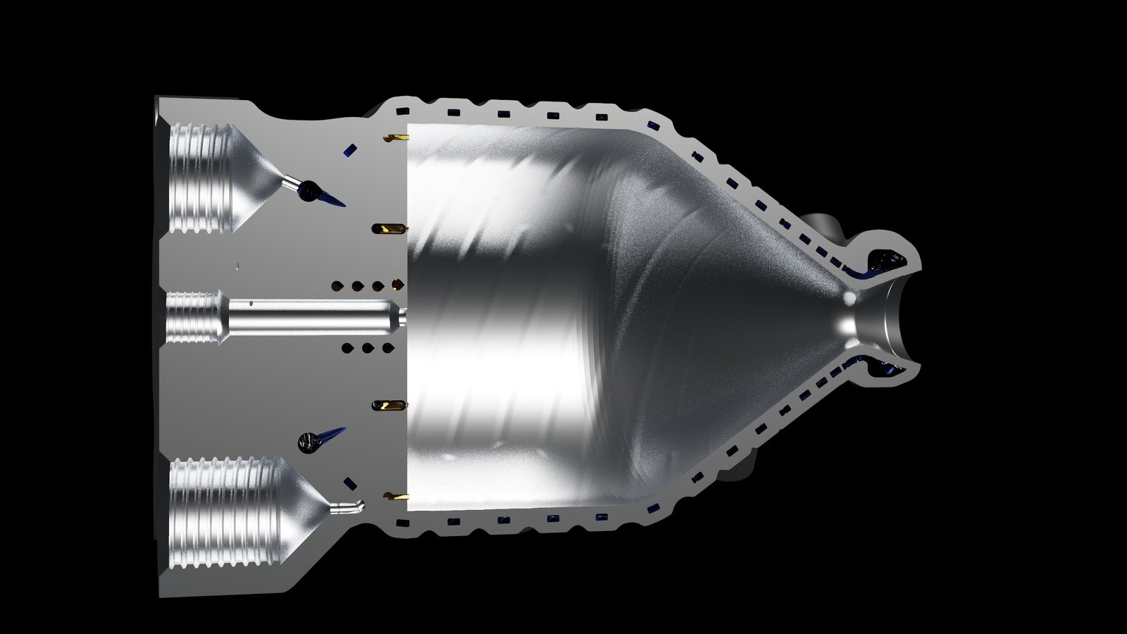
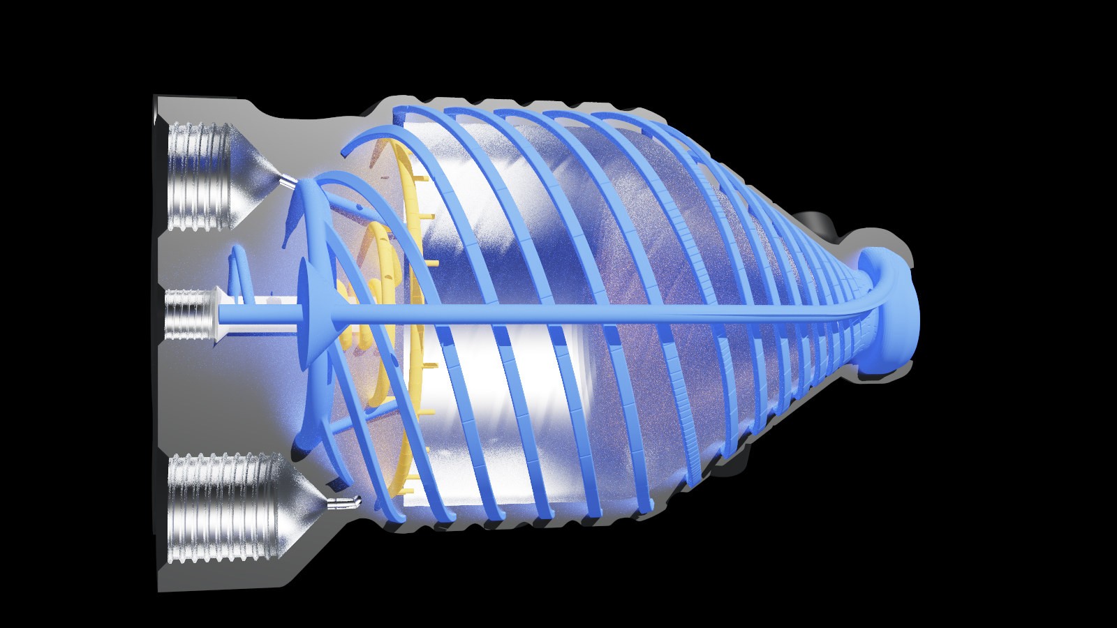
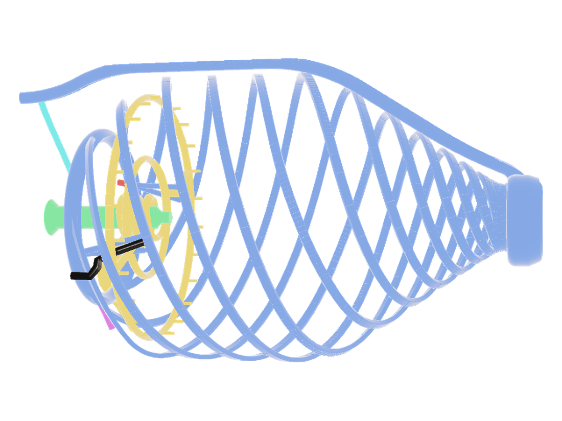
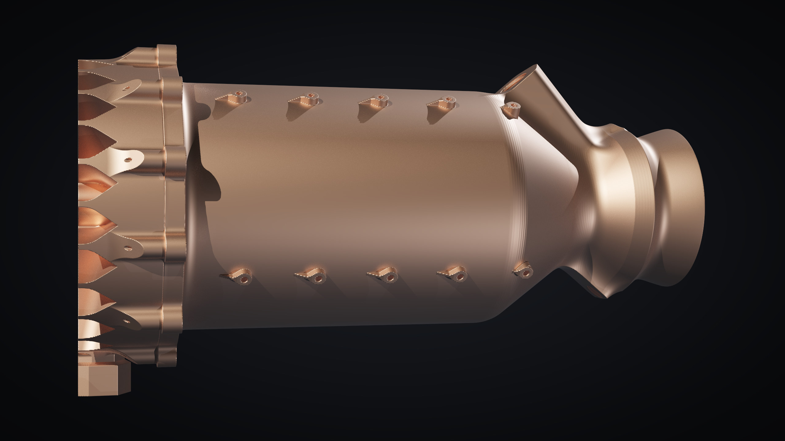
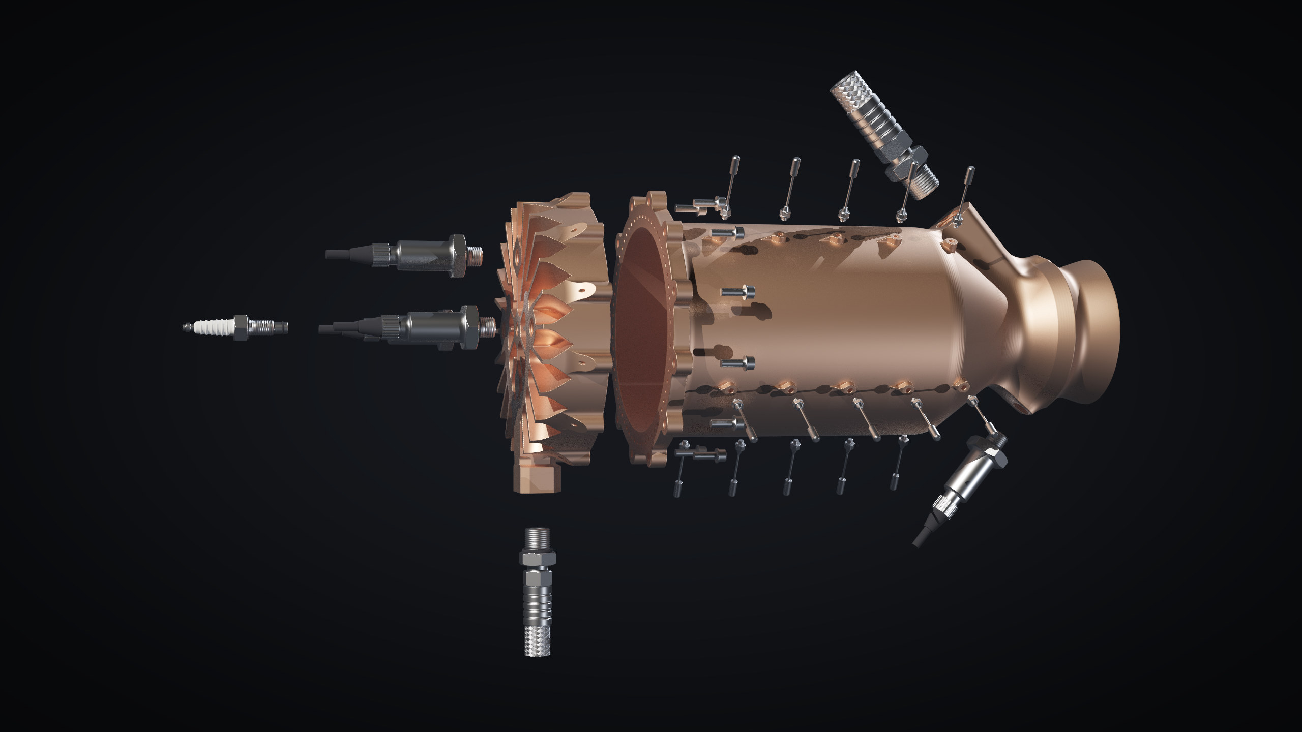
A 5 kN regeneratively cooled CuCrZr engine, printed as a bolted head and chamber
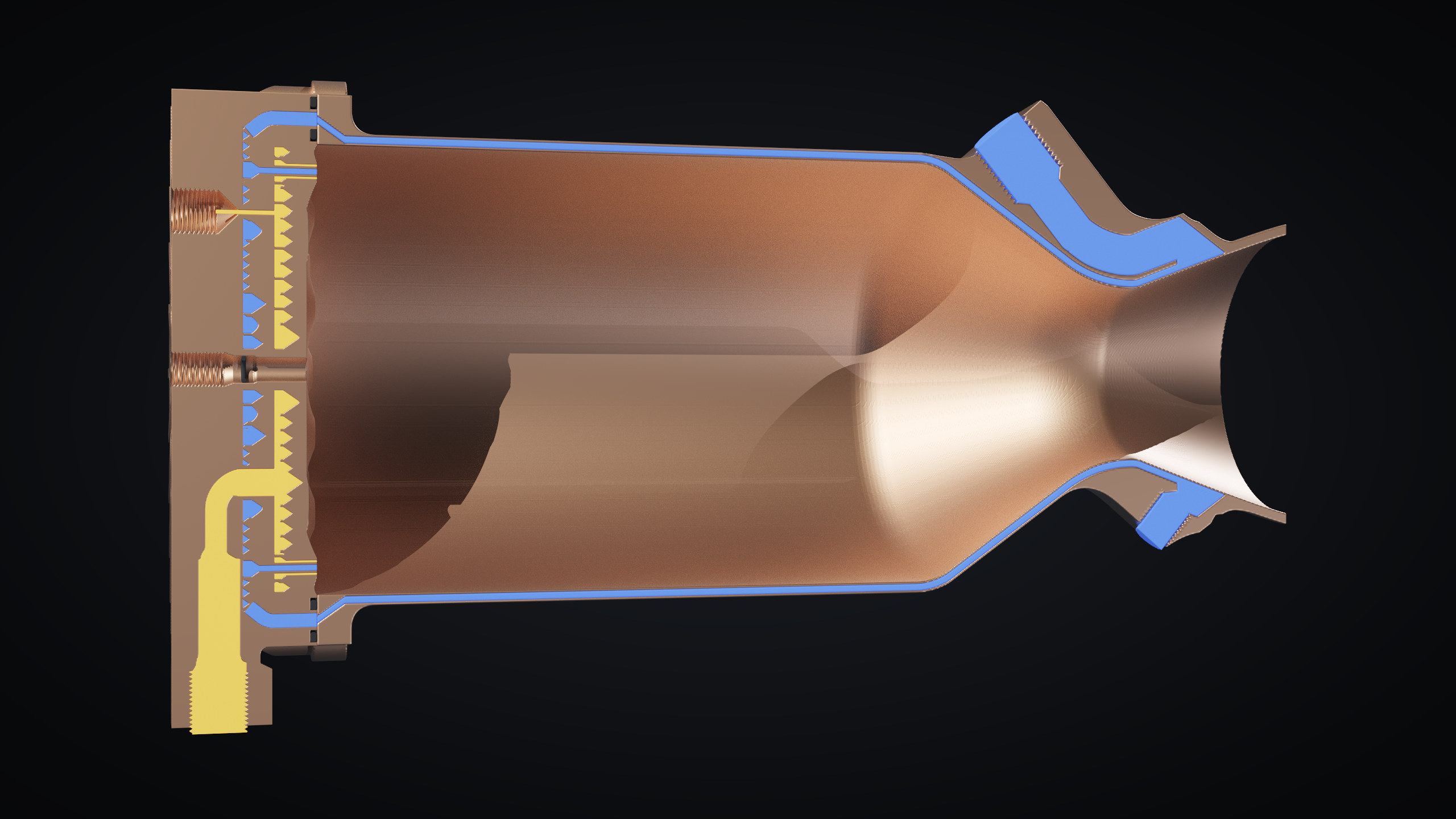
The second engine is in CuCrZr, the copper alloy that powder-bed printed regen chambers use, and is sized from the same combustion, nozzle and cooling code as the 50 N. Nitrous oxide cools 62 axial channels before it reaches the injector. The injector has twelve pressure-swirl coaxial elements in two rings, and eighteen small fuel-rich elements round the rim whose fuel lays a cooler layer of gas along the wall.
Ports, bosses and thermocouple lines are placed by the same solver as the 50 N, and a print audit checks every overhang and wall on the finished fields.
The material is one I have printed. In my final-year project on 3D-printed thrust chambers I tuned laser powder-bed fusion parameters to print CuCrZr on a conventional machine, where copper’s high reflectivity makes the powder hard to melt fully. The work ran from test coupons and calibration pieces to a printed small engine.
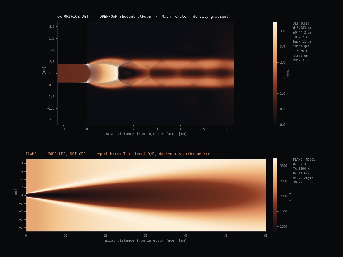
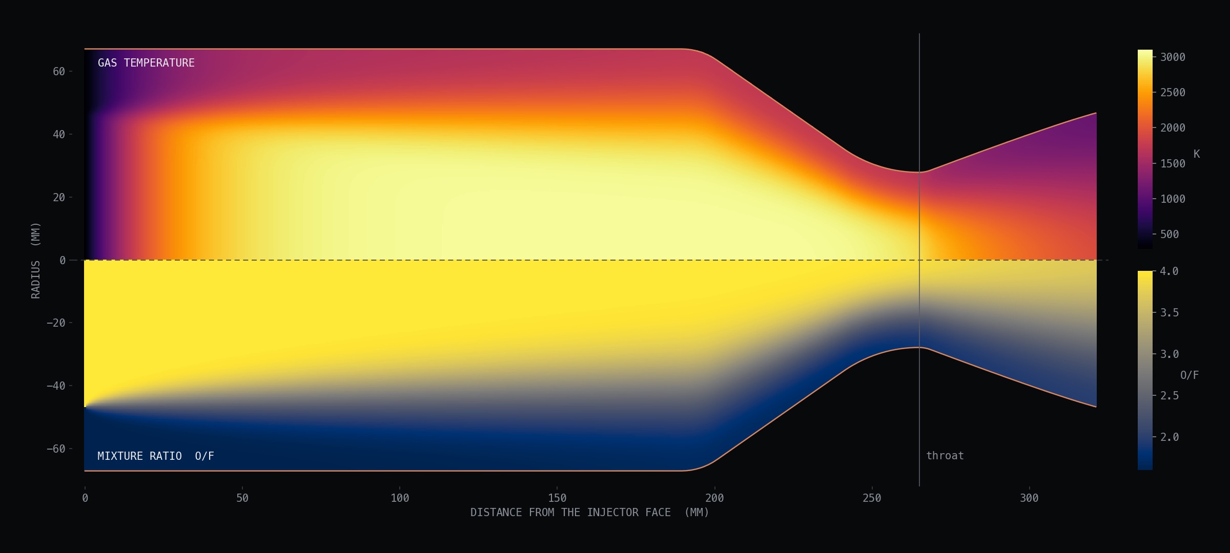
Hot gas and wall temperature
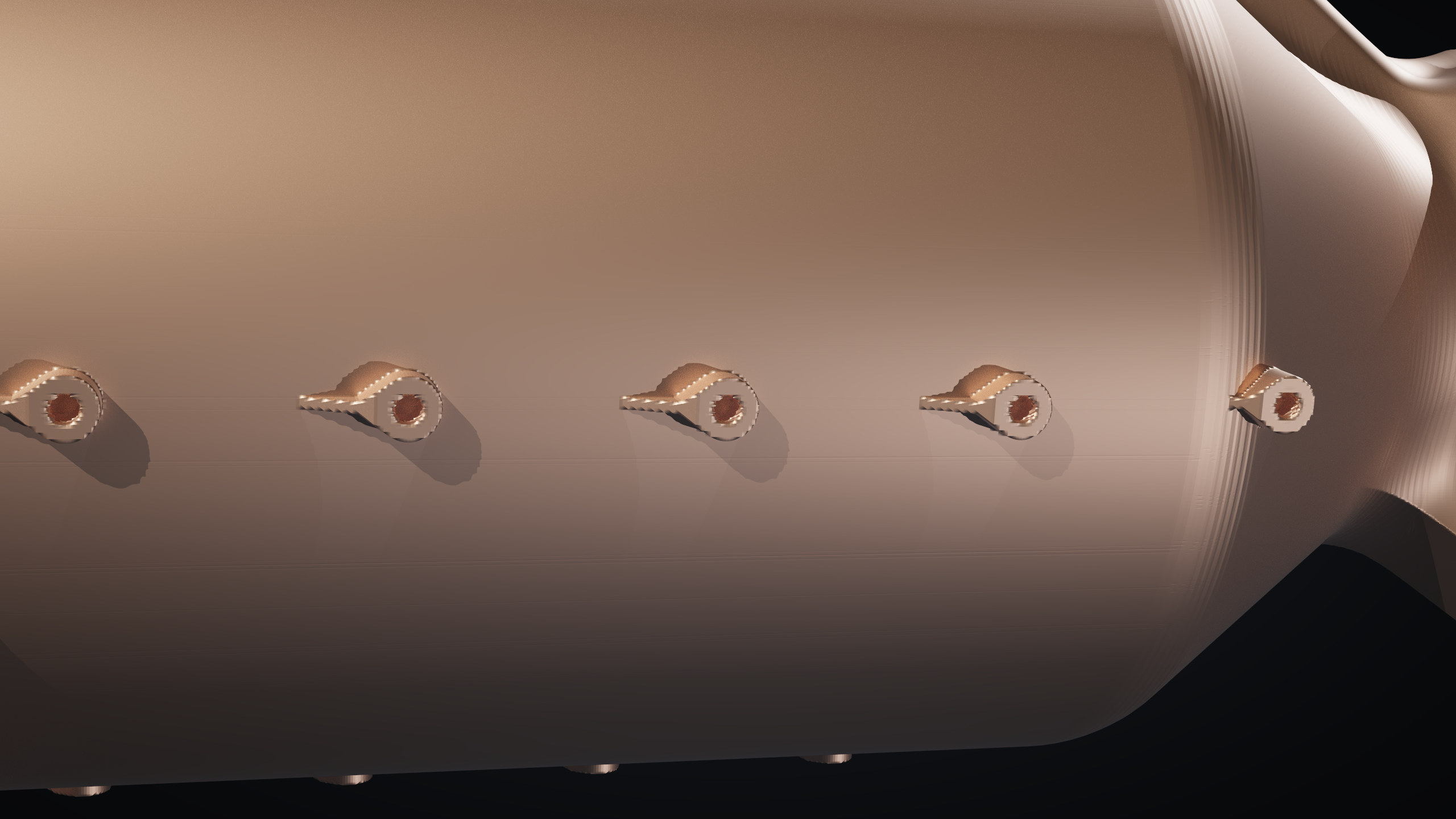
Cold-flow CFD of the injector head
Each propellant circuit of the head is meshed from the build's own fields and solved in OpenFOAM: steady RANS (k-ω SST) of the liquid at the design flow, from the inlet fitting through every passage and element into a slab of the chamber. About 3.9 million cells per circuit, 1500 iterations, each element's flow averaged over the last 300 and checked against an independent integration at four planes in each nozzle, within 2 %. It found two problems that every geometry gate had passed: one in the fuel circuit and one in the oxidiser circuit.
Fuel · found and fixedEighteen elements with no fuel
The first fuel run put 40 % more than design through the core elements and nothing through the rim: 0.0 g/s across eighteen elements, against a design 182 g/s. Without the rim's fuel-rich layer, the wall would have run in core gas.
Ports 0.15 mm short of their annulus
Each rim element's fuel enters through tangential ports 0.93 mm across, set 2.74 mm off the element axis to make swirl. Their inner edge stopped at 2.28 mm; the fuel annulus they feed ends at 2.13 mm. The core ports reached theirs by 0.05 mm, by coincidence. The build's contracts checked that passages stay apart, never that they join.
Every fuel annulus starts as a swirl chamber
The ports now open fully into a chamber at the plenum floor, coned at 55° down to the annulus so it prints without support. The posts round it grew to keep a 0.8 mm wall, the inner rim ring moved from r 49.5 to 48.5 mm, and the head layout was solved again.
Same mesh, same solver, flow restored
The rim now gets 148 g/s, 82 % of its design fuel, every rim element between 11 and 26 % low and the core 1 to 22 % high. A regression test now asserts that every tangential port, ox and fuel, core and rim, opens into its chamber.
The rim takes 68 % too much oxidiser
With 18 % less fuel as well, the rim elements run at O/F 2.9 to 3.5 instead of the 1.6 they were sized for, and take 23 % of the oxidiser against a design 14 %. Through the chamber model that puts the gas at the wall near 2900 K instead of 1770 K, so the fuel-rich layer the rim was added for would mostly be lost.
Nothing turns the flow into swirl
The oxidiser's tangential ports are cut only through the 0.8 mm wall of each swirl chamber, with open plenum beyond, so the flow crosses the wall 1 to 2° off radial against the 90° designed. The rim elements run as plain jets, discharge coefficient 0.48 to 0.52 against the 0.217 they were sized to; the core keeps some swirl, at 0.33. Swirl theory puts both at 0.22, so element size is not the cause.
Support rings lie across the flow
The plenum's concentric rings, sized for powder removal on the assumption that the flow ran along them, cross the oxidiser's radial path and drop its pressure in steps of 0.15 to 0.55 bar. The outer elements are fed at about 4.2 bar and the innermost at 2.1.
Sleeved ports and radial ribs
Each oxidiser port is now a bore in its own sleeve, closed round for two diameters past its chamber, and the plenum's ribs run radially, along the flow. A network calibrated on this CFD puts every ring within 3 % of design.
The oxidiser was solved on three meshes, the elements' cells halving each step (0.5, 0.25 and 0.125 mm; the finest about 7.9 million cells). The rim's excess goes +53 %, +68 %, +66 %. Between the working mesh and the finer one, the rim's total moves 1.6 %, the core's 0.3 % and the pressure drop 1.8 %, all inside a 5 % tolerance. The rim over-feed and its size are settled. Single elements are not: the shares within the rim still move 8 to 20 %, so the per-element bars show the pattern, not each element's exact flow.
The fuel can't use the coarse mesh: its 0.5 mm cells are as wide as the annular gaps the fuel leaves each element through, so the passages close and the solve stops.
Coolant manifold
Every section of the 5 kN, from the injector face to the nozzle exit: the CFD's speed and pressure through the head's passages, and the modelled gas temperature and mixture ratio down the chamber. Drag to turn the engine, scroll to slide the cut. Open the field viewer (about 16 MB, best on a desktop).